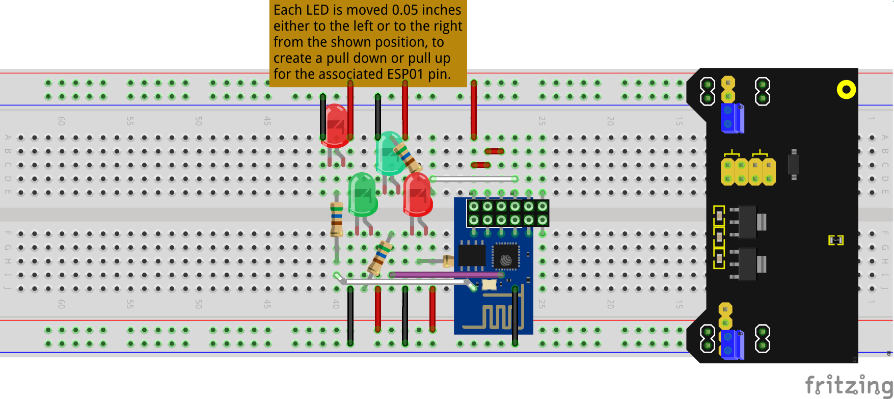
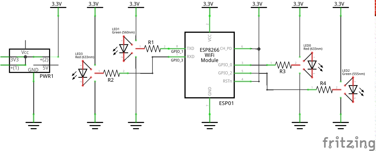
Post ESP8266 Boot Testing shows a setup for testing how an ESP01 board behaves on power up, with the GPIO pins in different states. This is a followup to that, with an updated Fritzing sketch, example testing code, and experimental results. The sketch has been adjusted slightly to both match my “as built”, and to better show how the breadboard circuit is intended to be used.
I also included my test Arduino sketch in the code view of the Fritzing sketch, with a comment block showing the main test results. In summary, the power up constraints to get the board to run the loaded program are not as sever as indicted in the documentation. It seems that as long as GPIO0 is not actively held low, the ESP8266 power on boot loads and runs the Arduino sketch. The testing included connecting a 470K Ohm resistor to ground. That also ran the loaded sketch. The 470K is large enough to act the same as leaving the pin unconnected (floating). It is a high impedance load.
Not tested yet, but that should mean that a FET (gate) connected to GPIO0 should not cause any problems either, so driving an active high N channel FET should work fine. Using a NPN transistor does not work. That provides enough of a load (like the LED) to actively pull the GPIO line low, causing the ESP8266 to power up in programming mode.
After uploading the testing code, the LEDs can moved left or right to provided pulldown or pullup loads, left out to leave the GPIO pin floating, or replaced by a large resistor to simulate a high impedance input to the next stage.
Testing shows that an LED on GPIO2 flickers once at power, whether it is acting as a pulldown or pullup. This occurs before the sketch takes over, and sets the pin mode and state. That is what the initial delay in the setup function is for. To be able to see the GPIO pin activity before the sketch takes over control. The same applies to GPIO1. GPIO0 only flickers when using a pullup load. With pulldown, programming mode is immediately active, and the blink is not detectable. No flicker is visible for LED loads on GPIO3.

