The ESP8266 chip boots into different modes based on the state of various pins at power up or reset. That means that projects using the chip need to make sure the electrical conditions are correct to get the chip to boot into the intended code, while also making sure that attached hardware that is (about to be) controlled by the chip initializes correctly. Without any bogus signals during power up or reset.
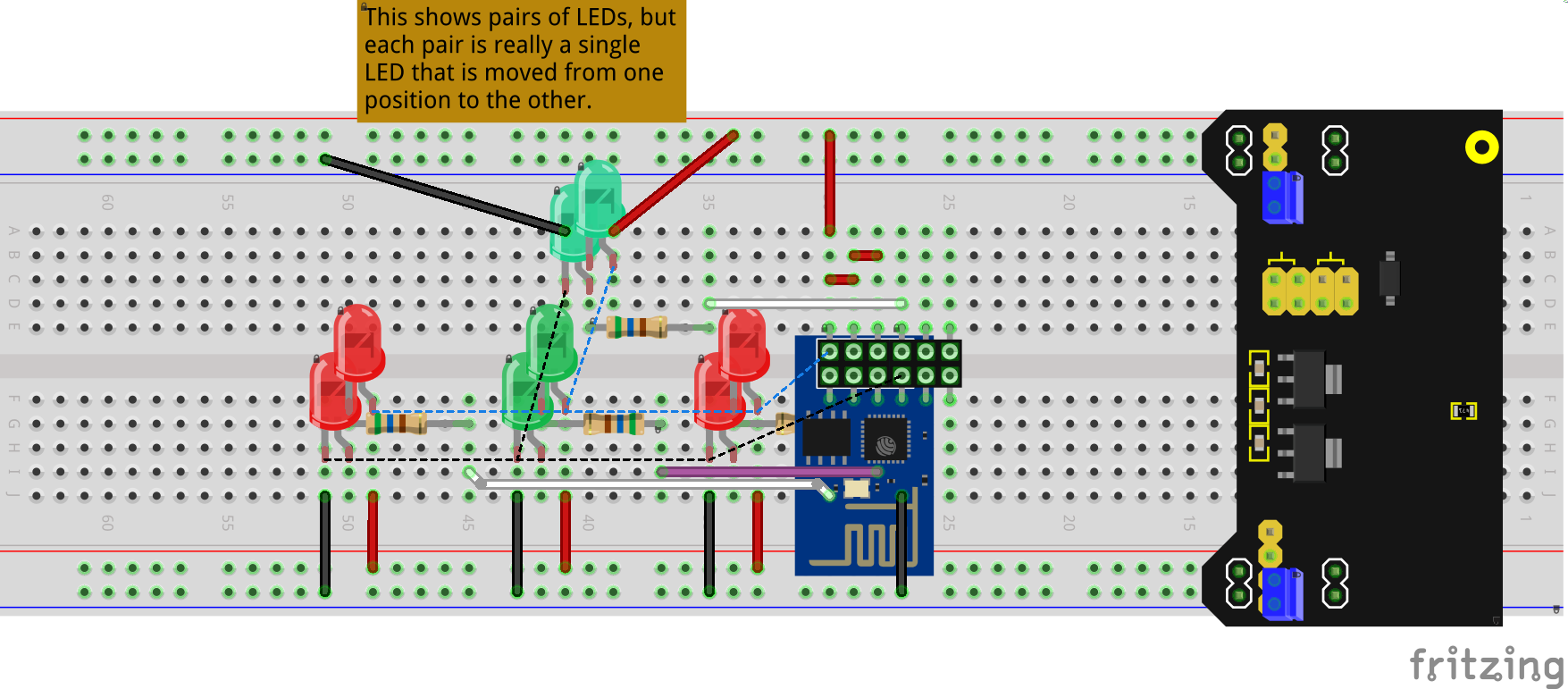
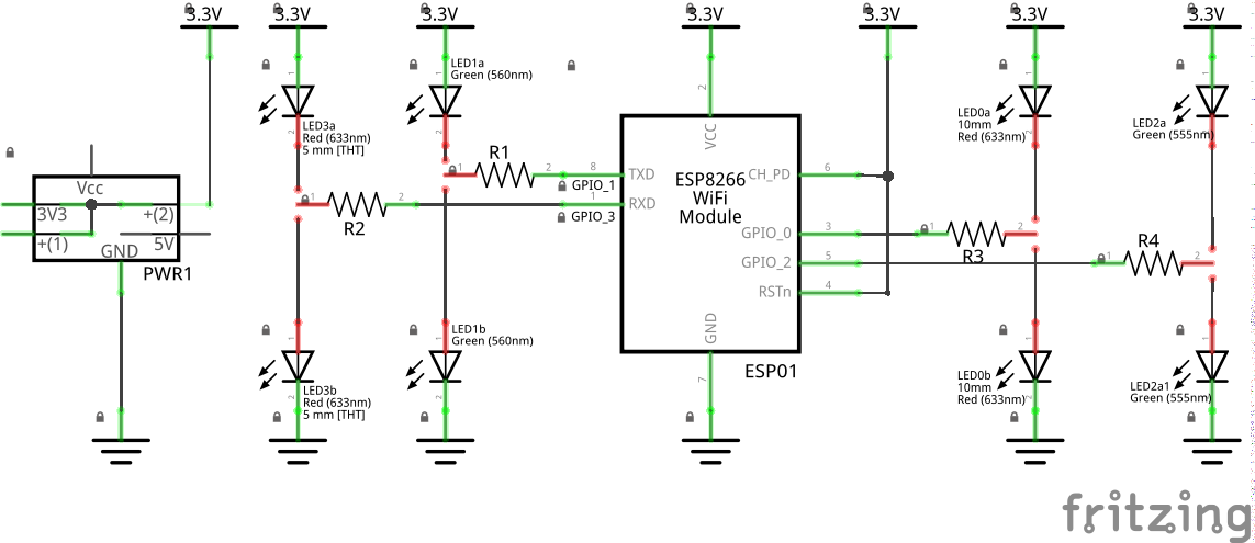
I created a small breadboard circuit using an ESP8266 (ESP01 board) that pulls each of the 4 GPIO pins to either ground or vcc through an LED. The pullup or pulldown can be changed by moving the LED one row over on the breadboard. This, combined with a simple sketch to blink the LEDs, allows easy testing of the expected boot mode, and some visual indication of what signals are present before the sketch gets full control. More rigorous test may be need to verify that initialization is correct, but many combinations can be eliminated by seeing that an LED blinks on power up, before the coded pattern starts being generated.
The circuit was input into Fritzing. The schematic view 2 LEDs almost connected to each GPIO pin. There are 2 LEDs shown on the breadboard view as well, but none connected to the actual pins. In reality, only one LED is used per GPIO pin. That single LED is moved one column left or right to act as a combination pullup or pulldown and visual state indicator.
After uploading the testing code, the LEDs can each be set to pullup or pulldown, and the power cycled to examine the initialization states. For starters, GPIO0 must be pulled high to have the ESP01 boot from the SPI flash memory, where the Arduino Sketch is stored. That leaves only 3 LEDs, a total of 8 combinations to check. To look for unacceptable ‘pulses’ when powering up. Below are png exports from that Frtizing sketch file. The starting state with no LEDs in circuit. After finding the combination(s) that work with the (test) code for a project, the LEDs could be moved into position, and copy of the sketch used as documentation.

